Introduction
The object of this paper is to demonstrate with a fairly simple example problem the use of AmpCalc for Windows. By using one of the standard NEC Code ductbank configurations, insight can also be gained into the manner in which the NEC assigns ampacity ratings to the cables in a ductbank.
Example Configuration
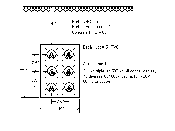
Refer to the figure below which illustrates the ductbank configuration utilized in this example. This configuration is identical to the six raceway ductbank in the IEEE Standard S-135 and in Figure 310.60(C)(3), Detail 3, of the NEC Code.
Performing A Single Type Calculation
Return to the Main form and the use the “Calculate | Calculation Options…” menu command or the Calculate icon to proceed to the Calculation Options form. Under Type of Calculation, select “Single” and under Parameter to Calculate select “Ampacity”. In this calculation, AmpCalc will treat all six cables as parallel conductors of the same circuit. A single ampacity will be calculated applicable to every cable in the system. This ampacity will be based on limiting the temperature of the hottest cables in the installation, (which are the two positions in the middle row), to the rated operating temperature of 75 degrees C. This is the manner in which the NEC and S-135 ampacities are calculated.
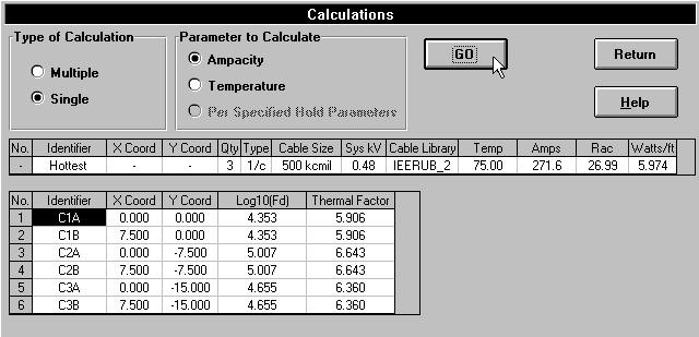
These cables have an calculated ampacity rating of 271.6 amps, which is very close to the IEEE Standard S-135 and the NEC code value of 273 amps.
Performing a Multiple Type Temperature Calculation
In the case just calculated, a single ampacity value was calculated for the six paralleled cable grouping making up a single circuit. Since the circuit ampacity was based on running the hottest middle cables at the rated operating temperature of 75 degrees C, it stands to reason that the top and bottom rows of cables will run at some lower temperature. This brings to mind some questions:
1. What is the actual temperature of each conductor when running at 271.6 amps?
2. What would be the ampacity of each conductor if each were run at rated temperature?
The standards provide no way to make these evaluations. However, for AmpCalc it is an easy task!
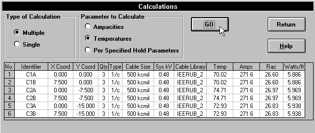
The data file for the second case of this example is ‘ex1b.ugs’. Scan through the position data and notice the only difference from the data in file ‘ex1a.ugs’ is that the “Specified Amps” for each position has been made equal to 271.6. Proceed to the Calculation Options form. Under Type of Calculation, select “Multiple”, and under Parameter to Calculate, select “Temperatures”. Click on “Go” to obtain the following results:
Performing a Multiple Type Ampacity Calculation
In summary, some observations from the previous cases include:
- The symmetry of the duct and the manner in which both cables of each circuit are placed in “thermally equivalent” positions would cause one to anticipate that the cables in each row will have the same temperatures. The results confirm this.
- Based on the temperatures of the six cables, it appears that the relative current carrying capability at each position pair will be in order from highest to lowest: Top row, Bottom row, Middle row.
- There should be a level of reduced C2 current loading and increased C1 and C3 loading where the temperatures of all three circuits will be equal to rated. Neither of the two cases looked at thus far meet this condition.
A calculation can easily be performed in response to the latter observation. Under Type of Calculation, select “Multiple” and under Parameter to Calculate select “Ampacities”. Click on “Go” to obtain the following results:
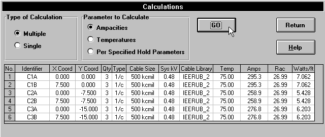
With this calculation, all conductors are operated at their rated 75 degree temperature. As expected, since the middle row runs the hottest, these cables have the lowest ampacity rating of 258.9, the bottom row is next with a rating of 276.8, and the top row has the highest rating of 295.3 amps. If this ductbank system consisted of three circuits of two 3-1/c triplexed cables each, i.e. each row of cables a separate circuit, the ampacities of circuits C1, C2, and C3 would be 590, 518, and 554 amps per phase respectively. If each circuit is operated within these ampacities, none of the cables will operate beyond rated temperature. With all else being equal, the heating of a cable is a function of its underground depth, and the interference effects of heat from other cables in the same installation. In this example, the middle row has the lowest ampacity rating because of the combination of being lower in the earth than the top row, together with the “thermal blanketing” effect of the first and last rows of cables.
Ampacity Calculations with Six 1/c Cables per Duct
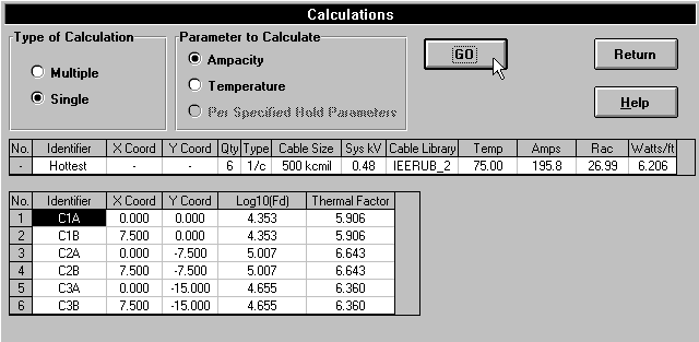
Data file ‘ex1c.ugs’ illustrates the use of two sets of triplexed 1/c cables per duct position, or 6-1/c cables per duct. The results, based on a Single Ampacity calculation, are shown below.
Note the derate of the conductor current carrying capability from 272 to 196 amps. Putting in more copper into the same underground duct configuration will yield a higher overall system capacity, but not in proportion to the additional cross section of copper due to mutual heating effects. If the entire ductbank in this example is utilized for a single three phase circuit, with 3 cables per duct, the circuit consists of a total of 6 conductors per phase with a total ampacity of 6 x 272 = 1,632 amps per phase. With two sets of triplexed 1/c cables at each position, the amount of copper in the installation has increased 100%, but the total ampacity has only increased to 12 x 196 = 2,352 amps per phase, a 44% increase.
Voltage Drop, Load Flow, Duct Fill and Jam Calculations
To assist in underground cable system circuit design, in addition to the ampacity calculations, AmpCalc offers voltage drop, load flow duct fill and jam calculations. The former calculations are provided in each position data entry form, once the user has entered sufficient information to make the calculation.
Load the ‘ex1a.ugs’ file back into AmpCalc, go to the position data entry form for position 1 and note the voltage drop calculation result duplicated below.
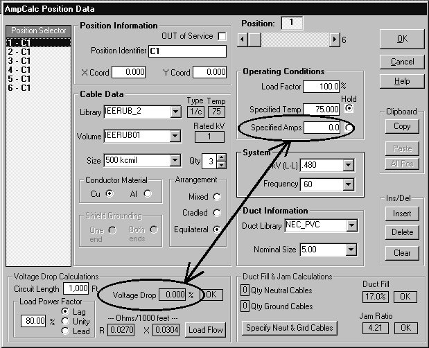
The voltage calculation remains at zero because a value greater than zero for ‘Specified Amps’ must be entered. This is the current that is assumed to be in the circuit for voltage drop and load flow calculation purposes.
Load file ‘ex1b.ugs’ file back into AmpCalc, go to the position data entry form for position 1 and note that a non-zero 3.9% voltage drop calculation is now depicted, since a non-zero entry for ‘Specified Amps’ now exists. This voltage drop is also based on a 1000 foot cable distance and a load power factor of 80% lagging.
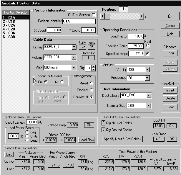
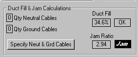
Note that the duct fill and jam calculations are satisfactory. Change the duct size to 3.5″ to obtain the following jam warning although the duct fill is still acceptable.
Calculations with Metric Cables
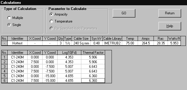
Data file ‘ex1d.ugs’ illustrates the use of metric cable sizes in AmpCalc with a selected size of 240 mm2 . When entering metric cable sizes, all other AmpCalc dimensional inputs remain in English units..
Having completed these example cases, the user is encouraged to load either example data files into AmpCalc, make changes to the data, and run additional calculations.
For instance, try revising the data from ‘ex1b.ugs’ by changing the “Specified load current” fields from 271.6 to 295.3, 258.9, and 276.8 amps respectively for C1A/B, C2A/B, and C3A/B. Using a “Multiple” and “Temperature” calculation, AmpCalc should then calculate temperatures of 75.00 degrees C for all cables – or else very close within rounding errors!
